
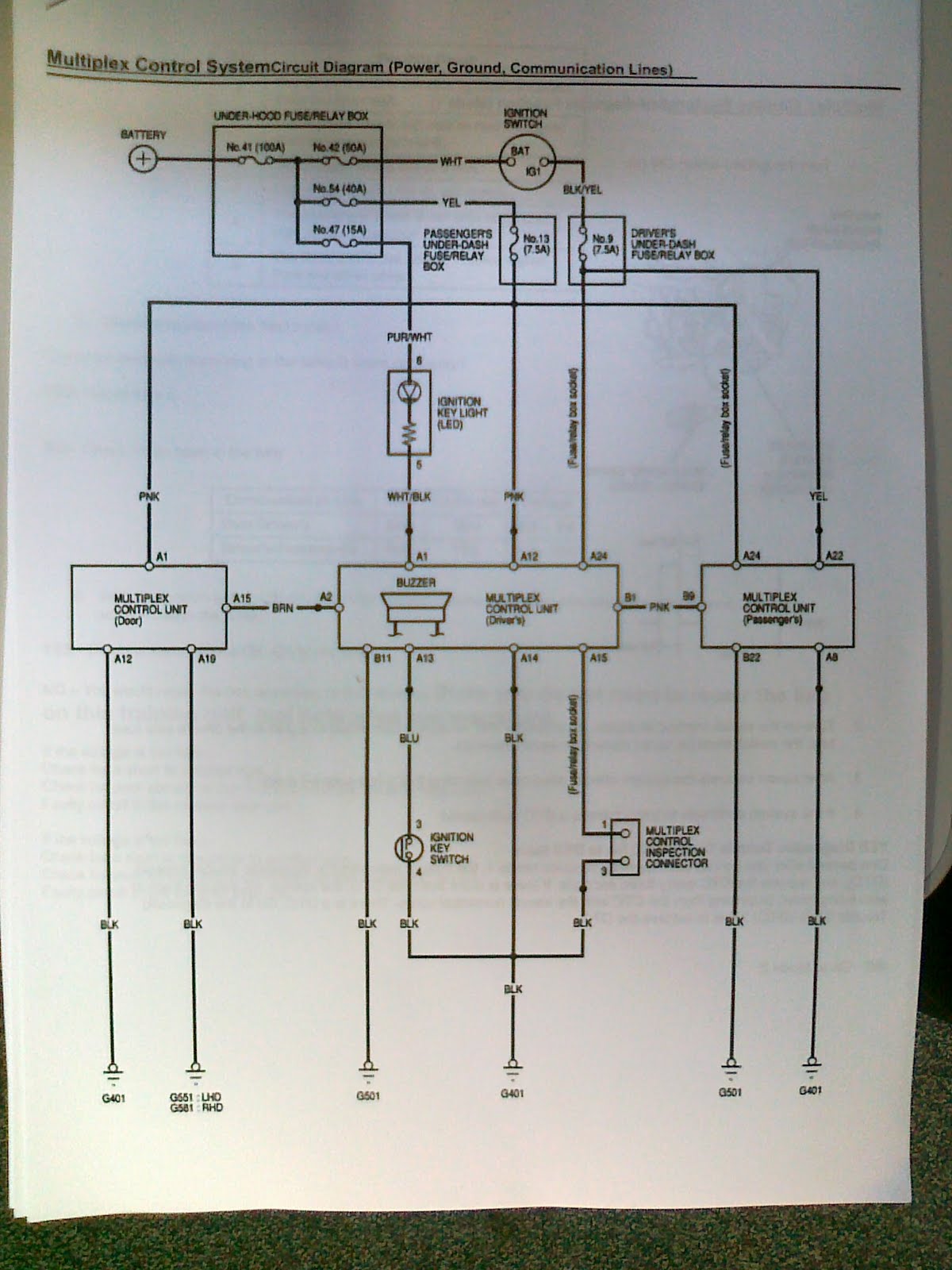
Starting from the wiring diagram below we can see that Door Multiplex Control Unit is connected to the Driver's Multiplex Control Unit by brown wire between A15 and A2. Driver's Multiplex Control Unit is connected to the Passenger's Multiplex Control Unit by pink wire between B1 and B9. The earth connection is provided by black wire for Door Unit through A12 and A19, for Driver's Unit through B11 and A15, for Passenger's Unit through B22 and A8. Power supply wire has pink colour and is connected to the A1, A12, and A24 accordingly for Door Unit, Driver's Unit, and Passenger's Unit.
The video clip below shows that window on the driver side goes up but doesn't go down.
Because there is still communication between the node and actuator while we put the window up but we cannot hear clicking noise from the relay trying to put the window down I came to the preliminary conclusion that there is a fault with a signal out. We must check this signal, the relay connection, or relay itself.
Following the instruction from manufacturer we put the system into the mode1 and tried to find possible faults. However, DTC doesn't allow identifying this fault. There is no beep signal from buzzer.
In this case we cannot prove preliminary conclusion.
So that, we come to the continuity test which result is on the photo below:


From here we shifted to the Mode2 and captured
this part of the experiment on this video:
Following the manual we can see that beeper sounds once what means that circuit line is ok. Step by step we clarified that we've got the input, communication but we don't have an output.
We check voltage supply for the switching relay. Pin#30 has 12 volts voltage. But nothing comes to the pin#86 from the Passenger Node.


Wiring diagram copy below shows how the door electromotor is wired into the circuit.

Once we pull the switch up we have a signal for the relay to connect the motor to the power supply on the one side. The other side of the electromotor is grounded. It rotates then. In opposite direction we don’t have a signal to the relay. Thus, one side of the electromotor is grounded but there is no voltage supply on the other side. The motor is not acting.
By going through the experiment step by step and dividing the system onto the inputs, communication, and outputs we diagnosed the fault accurately and quite quickly. It means that different procedure compared to the analogue system signal transferring diagnostics still allows working on it effectively. The important thing is to understand the structure of digital signal system transferring and follow the manufacturer manual logically.
In this particular case we could not put the system into the sleep mode and measure the time it takes and parasitic draw. In practise, the ampere should change from 70 mA to less than 10 mA.( page5 Multiplexing Control System Instruction)
No comments:
Post a Comment